Plate distortion in flexography: how to calculate it
One of the biggest questions in flexography. Here are three ways to calculate plate elongation: two with math formulas and one hands-on method that will surprise you.

This is one of the biggest questions among people who do flexography, so we put together three ways to calculate elongation: two using math formulas, and one completely different method that will surprise you.
Why is distortion applied in flexography?
You are probably used to applying an elongation percentage to flexo files, but not sure why.
If you take a photopolymer plate (also called a "cirel" in some countries) and lay it flat, the bottom (Xd) and the top (Yd) have the same length.
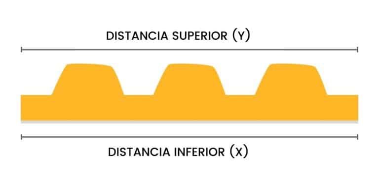
However, when the plate is wrapped around a cylinder, its surface starts to stretch. The distance along the top of the plate becomes greater than the distance along the bottom.
Because a photopolymer plate is imaged completely flat, the original file must be reduced — distorted — only in the direction in which the plate will be wrapped around the cylinder's circumference, so that once mounted it has the correct size.

The distortion percentage is simply the ratio Xd / Yd, where Xd is the circumference of the inner circle and Yd is the circumference of the outer circle.
Math formula
Let's start with something simple: the difference between the radius, the diameter and the perimeter of a circle.
The radius is the distance from the center to the edge of the circle. Its formula is diameter ÷ 2.
The diameter is the straight-line distance from edge to edge. Its formula is perimeter ÷ π (π ≈ 3.14159).
The perimeter is the edge of the circle — the total distance around it. Its formula is 2 × π × R (π ≈ 3.14159).
So there are two circumferences we need to find: the top of the plate (Yd) and the base where the plate is mounted (Xd).
The distortion formula is:
% Distortion = Xd / Yd
Which we can rewrite as:
% Distortion = 2πR₁ / 2πR₂
Where R₁ is the radius of the inner circumference and R₂ is the radius of the outer circumference of the plate.
R₁ and R₂ depend on the plate thickness (P), the mounting-tape thickness (T), the cylinder radius (C) and the thickness of the plate's polyester backing.
It is worth noting that one of the key elements that keeps the plate from stretching on the bottom is the plate's polyester backing (mylar), which is very strong and prevents the base from stretching during mounting. If you have seen flexo plates, you know that base is highly resistant.
Continuing, we calculate the radius of the two circumferences.
R₁ equals the cylinder radius plus the mounting-tape thickness plus the plate's polyester-backing thickness.
R₁ = C + T + M
R₂ equals the cylinder radius plus the mounting-tape thickness plus the plate thickness.
R₂ = C + T + P
So our elongation formula becomes:
% Distortion = (C + T + M) / (C + T + P)
Distortion from the repeat length
To find the distortion percentage from the repeat length (RL), understand the following.
The repeat length is the perimeter of the plate's circle at the top when mounted (the top perimeter). With RL we can find the radius of that circumference, which is Yd.
To find Xd, we subtract the plate height from Yd — the plate (P) minus the polyester backing (M). It sounds complex, but here is an example.
The formula: % Distortion = [RL ÷ (2π) + (M − P)] / [RL ÷ (2π)]
For our example: a job with a 25" repeat length using a 0.067" gauge plate.
Plate (P) = 0.067" or 1.702 mm
Polyester backing (M) = 0.005" or 0.127 mm
Repeat (RL) = 25" or 635 mm
% Distortion = [635 ÷ (2 × 3.1416) + (0.127 − 1.702)] / [635 ÷ (2 × 3.1416)]
% Distortion = 99.4885 / 101.0633
% Distortion = 0.9844 or 98.44%
The distortion to apply to the job in the print direction is 98.44%.
Distortion from the distortion factor
We saw the more complex method; now a very practical one, using an elongation constant based on the plate gauge.
This constant, or C factor, was found after extensive testing and is summarized in the following table.
| Plate gauge | C factor |
|---|---|
| 1.14 mm – 0.045″ | 6.10 |
| 1.70 mm – 0.067″ | 9.89 |
| 2.54 mm – 0.100″ | 15.16 |
| 2.84 mm – 0.112″ | 17.08 |
| 3.94 mm – 0.155″ | 23.94 |
If you want to know where the C factor comes from, it is calculated with this formula:
C factor = (2π) + (M − P)
Note: the polyester backing for the 1.14 mm gauge is 0.178 mm; for the rest it is 0.127 mm.
And the formula using the C factor is:
% Distortion = [1 − (C factor / RL)] × 100
Using the same data as before:
% Distortion = [1 − (9.89 / 635)] × 100
% Distortion = 98.44%
A simple, hands-on method
This is one of the ways our clients have determined elongation when they don't have the data the formulas need.
It is very simple. Take a piece of photopolymer plate longer than the roll's circumference, with an image on it (preferably a solid). Apply the mounting tape you normally use and stick it to the roll.
Because the plate is longer than the roll's circumference, the two ends will meet and one will overlap the other. When that happens, make a mark with a pen right where they overlap — a long mark is recommended.
Then peel off the plate, lay it on a flat surface and, with a tape measure, measure lengthwise from the mark to the start of the plate. That measurement is what the files should have once elongated when that cylinder is used to print.
This comes from the experience of supporting and advising many printers. If you need help with this kind of calculation or anything else, our team is fully available to support you.